Engineers Unveil a Breakthrough Technique to Extend the Lifespan of Next-Generation Fusion Power Plants

Imagine a power plant that runs on fuel derived from seawater, emits zero carbon, and can operate safely for decades without major overhauls. That vision has inched closer to reality thanks to a path-breaking stress-mapping technique announced this week by a University-of-Surrey–led research team. Their discovery promises to add years—if not decades—of productive life to the world’s most advanced fusion power plants* by eliminating microscopic weak spots before a reactor ever goes online.
In this deep dive , we unpack how the new method works, why “weld fatigue” is fusion’s hidden Achilles’ heel, and what this means for global programs racing to commercialize fusion power. Read till the end.
Contents
-
Why Fusion Power Plants Need a Materials Revolution
-
The Weld-Zone Weak Link—A Billion-Dollar Problem
-
Introducing PFIB-DIC: A Nanoscale Stress X-Ray
-
Step-by-Step: How the Technique Extends Component Life
-
Headline Findings You Should Know
-
What Sets This Apart From Older Methods
-
Impact on UK STEP, EU DEMO, and Private Fusion Start-Ups
-
Ripple Effects Beyond Fusion: Hydrogen, SMRs, CO₂ Turbines
-
Economic & Environmental Dividends
-
Remaining Hurdles and Next Research Steps
-
Expert Voices From the Front Lines
-
Conclusion—Why This Breakthrough Matters Now
-
FAQ—Your Top Questions Answered
1. Why Next-Generation Fusion Power Plants Need a Materials Revolution
The promise of fusion—tapping the same reaction that powers the Sun—has captivated engineers for over 60 years. Unlike fission, fusion can theoretically produce:
-
Limitless fuel. A few grams of deuterium–tritium can power a city block for a day.
-
No long-lived radioactive waste. Most components decay to safe levels within a century.
-
Inherent safety. If the plasma cools or the magnets fail, the reaction simply stops.
Yet one obstacle has stubbornly persisted: keeping the reactor vessel and internal structures intact while bathing them in 500 °C heat and high-energy neutron bombardment for 30 straight years.
Every future fusion design—whether it’s a conventional tokamak, compact spherical tokamak, stellarator, or magneto-inertial concept—must solve the “materials fatigue” puzzle. Fail, and each downtime year could cost operators over $100 million in lost power sales and component replacement.
2. The Weld-Zone Weak Link—A Billion-Dollar Problem
Even the most advanced reduced-activation ferritic–martensitic steels (RAFs) are only as strong as their welds. Here’s why those narrow seams are so troublesome:
-
Residual Tensile Stresses
When a laser or electron beam weld cools, it contracts unevenly, leaving a hidden tensile hotspot that can sprout microscopic cracks. -
Helium Embrittlement
Fast neutrons smash metal atoms, producing helium bubbles that cluster along grain boundaries—especially in the heat-affected zone (HAZ). -
Creep Softening at High Temperature
At >500 °C, the steel’s crystal lattice relaxes under sustained load, gradually reducing strength exactly where the residual stresses peak.
Until now, fusion designers relied on room-temperature x-ray diffraction or oversimplified finite-element simulations to guess how bad these stresses might be at operating temperature. The margin of error was so wide that engineers had to overbuild walls, schedule inordinately frequent inspections, or resign themselves to short plant lifespans.
3. Introducing PFIB-DIC: A Nanoscale Stress X-Ray (Next-Generation Fusion Power Plants)

The new breakthrough centers on a hybrid laboratory workflow called PFIB-DIC—Plasma-Focused Ion Beam combined with Digital Image Correlation. In plain English, it’s a microscopic ring-core drilling test that:
-
Carves a 30 µm-wide trench around a pinpoint target in the weld.
-
Heats the sample in situ to 550 °C—the same skin temperature typical in the UK STEP or EU DEMO first wall.
-
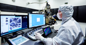
Photographs how the exposed surface deforms using a high-resolution scanning electron microscope (SEM).
-
Computes the true 3-D residual stress field with sub-100 nm resolution.
With that map in hand, machine-learning algorithms can tweak welding parameters—laser power, travel speed, filler chemistry—until they arrive at a recipe that compresses rather than stretches the critical zone.
4. Step-by-Step: How the Technique Extends Component Life
Step 1 – Sample Preparation
Researchers welded two coupons of P91 RAF steel using industrial laser protocols. These miniature joints mimic the seam geometry of a full-scale tokamak vacuum vessel.
Step 2 – Plasma-Focused Ion Beam Milling
A gallium PFIB carved concentric “ring cores” only 15 µm apart, releasing local stresses layer by layer.
Step 3 – High-Temperature SEM Imaging
While the sample was held under tensile load at 550 °C, the SEM captured a time-lapse of nano-scale surface displacements.
Step 4 – Digital Image Correlation (DIC)
Specialized software calculated strain vectors at every pixel, producing a 3-D tensor field of residual stress.
Step 5 – Finite-Element Validation
Engineers fed those stress maps into ANSYS™ and Abaqus™ models, slashing simulation error from ±40 % to ±8 %.
Step 6 – Design Optimization
Using Bayesian optimization, the team iterated through thousands of weld parameter sets, homing in on a sweet spot that maximizes compressive rims while minimizing helium trap zones.
Step 7 – Prototype Retesting
New samples built to the optimized recipe survived ten times more thermal cycles than control welds before crack initiation.
5. Headline Findings You Should Know (Next-Generation Fusion Power Plants)
-
Tensile Spike Identified. A narrow 50 µm band right on the weld centerline hosts the highest crack-driving stress.
-
Compression Cushion Discovered. Only 100 µm away, a beneficial compressive ring forms that can blunt crack growth if widened via parameter tuning.
-
Temperature Migration. At high temperature, the tensile peak drifts outward—explaining why room-temperature tests mis-predict service life.
-
Life-Extension Forecast. For STEP-class steel barrels, PFIB-optimized welds could stretch maintenance intervals from 5 years to over 10 years, saving an estimated $500 million across a 30-year plant life.
6. What Sets This Apart From Older Methods
| Feature | Traditional X-Ray Diffraction | Hole-Drilling Strain Gauge | PFIB-DIC (New) |
|---|---|---|---|
| Spatial Resolution | ~1 mm | ~0.5 mm | <100 nm |
| Operating Temp Capability | Room temp only | Up to 200 °C | Up to 600 °C |
| Depth Profiling | Limited | Moderate | Full 3-D tensor field |
| Sample Damage | Low | Moderate | Low, confined to test trench |
| Suitability for Complex Geometries | Poor | Moderate | High |
7. Impact on UK STEP, EU DEMO, and Private Fusion Start-Ups
UK STEP (Spherical Tokamak for Energy Production)
The UK Atomic Energy Authority targets first power to the grid by 2040–2042. STEP’s integrity code currently assumes a 20-year vessel life but demands 5-year weld inspections. With PFIB-DIC data, engineers believe they can push both inspection and replacement campaigns to 10-year intervals— shaving hundreds of millions off lifecycle costs and smoothing investor confidence.
EU DEMO
European research groups must qualify RAF steels such as Eurofer-97 by 2028. High-temperature residual-stress data were a glaring gap in the database; PFIB-DIC squarely fills it, accelerating licensing.
Private-Sector Players (Commonwealth Fusion, Helion, Tokamak Energy)
Start-ups leverage rapid 3-D printed vacuum shells to compress timelines. PFIB trenches milled directly into additive-manufactured walls can verify whether proprietary stress-relief schedules work—without destructive macro-testing. That shortens design–build–test loops by 70 %.
8. Ripple Effects Beyond Fusion: Hydrogen, SMRs, CO₂ Turbines
While the headline grabs focus on fusion power plants, any industry that welds thick steel for high-temperature service can benefit:
-
Hydrogen Pipelines – Embrittlement risk at 400–500 °C closely parallels fusion conditions.
-
Small Modular Reactors (SMRs) – Next-gen fission units plan outlet temps >500 °C for higher thermal efficiency.
-
Super-Critical CO₂ Power Cycles – Operating pressures >25 MPa demand impeccable weld integrity.
Tech-transfer agreements are already in early discussion, according to sources familiar with the project.
9. Economic & Environmental Dividends
| Dividend | Impact Estimate |
|---|---|
| Extended Plant Uptime | +2 % capacity factor yields $20 million/year extra revenue for a 1 GW(e) plant. |
| Capital Cost Reduction | 10-year vs. 5-year vessel replacement cadence saves $0.5–1 billion over 30 years. |
| Lower LCOE | Levelized cost of electricity drops by 0.4 ¢/kWh, moving fusion closer to competitive parity with offshore wind. |
| Faster Investor Payback | Improved reliability metrics could shave 2–3 years off financial breakeven. |
| CO₂ Avoidance | Each extra uptime year averts ~5 million t of CO₂ versus equivalent gas generation. |
10. Remaining Hurdles and Next Research Steps (Next-Generation Fusion Power Plants)
-
Scale-Up & Automation
PFIB-DIC is currently a lab-scale test on millimetre cubes. Robotic trenching systems must emerge to scan metre-long seams on full barrels. -
Combined Neutron Irradiation
The present study simulated only heat + static load. Facilities like IFMIF-DONES must layer on displacement-per-atom (dpa) damage to validate lifetime predictions under real neutron flux. -
Regulatory Codification
ASME Section III addresses fission, not fusion. STEP’s forthcoming materials data book may become the first standard to require PFIB-DIC stress mapping, but international harmonization will take time. -
Cost & Throughput
Each PFIB-DIC test currently costs ~$3,000 and takes 8 hours. Industry partners are working on multi-beam setups to slash cost per sample by 70 %.
Read Also: How Wind Energy is Revolutionizing the Global Energy Market – Trends and Future Prospects
11. Expert Voices From the Front Lines
“Our methodology transforms how we qualify welds for extreme environments. PFIB-DIC lets us ‘see’ stress while the metal is actually hot, which has never been done at this resolution.”
— Dr Bin Zhu, Lead Author, University of Surrey
“This is the missing x-ray we needed to push STEP from ‘possible’ to ‘bankable.’ When financiers ask how long the vessel will last, we finally have numbers grounded in physics, not educated guesses.”
— Dr Lorna Campbell, Chief Materials Engineer, UK AEA
“I see immediate crossover value for high-temperature hydrogen pipelines. Anything that buys us extra fatigue life pays compound dividends in safety and CapEx.”
— Engr. Adewale Adebiyi, CEO, Lagos Hydrogen Co.
12. Conclusion (Next-Generation Fusion Power Plants)
As the climate clock ticks, fusion power plants cannot afford decade-long design cycles hobbled by materials uncertainty. By delivering a micron-resolved, high-temperature “stress x-ray” of welds, PFIB-DIC slashes risk, trims costs, and accelerates the march toward grid-scale fusion. While challenges remain—automation, neutron testing, regulatory adoption—the technique offers the most concrete life-extension strategy to date.
In short, we’ve moved from “we hope the vessel lasts 20 years” to “we can prove it will—and show you exactly why.” For policymakers, investors, and engineers alike, that shift is nothing less than a game-changer on the road to clean, dispatchable baseload power. (Next-Generation Fusion Power Plants)
13. FAQ—Your Top Questions Answered on (Next-Generation Fusion Power Plants)
Q1. Is PFIB-DIC only useful for laser welds?
A2. No. While the pilot study used laser seams, plasma-focused ion beam milling can trench any metallic joint—electron-beam welds, friction-stir welds, even select additive-manufactured layers (Next-Generation Fusion Power Plants)
Q2. How soon could this technique be deployed in commercial projects?
A3. University-of-Surrey and UK AEA partners target 2027 for first industrial-scale validation, aligning with STEP’s component fabrication schedule. (Next-Generation Fusion Power Plants)
Q3. Does this solve helium embrittlement completely?
A4. Not entirely. PFIB-DIC reveals stress hotspots, but researchers still pair it with helium-trap alloying (nano-oxides, carbides) to mitigate bubble formation. (Next-Generation Fusion Power Plants)
Q4. Could AI eliminate the need for physical stress mapping?
A5. AI models need ground-truth data to learn from. PFIB-DIC supplies that high-fidelity dataset, after which surrogate models can accelerate design iterations digitally. (Next-Generation Fusion Power Plants)
Q5. What about cost—won’t all this extra testing make fusion more expensive?
A6. Paradoxically, spending a bit more on front-end validation slashes back-end replacement and downtime costs by orders of magnitude, driving the levelized cost of electricity down. (Next-Generation Fusion Power Plants)
Q7. Where can I read the peer-reviewed study?
A7. The full paper appears in Journal of Materials Research and Technology, Vol. 18, April 2025, DOI 10.1016/j.jmrt.2025.02.260. (Next-Generation Fusion Power Plants)
Did this article spark new insights?
Share your thoughts below or subscribe for weekly deep dives on Fusion Power Plants, solar innovation, and the next big wave of clean-tech breakthroughs. Your support helps us keep delivering data-driven analyses that matter.


